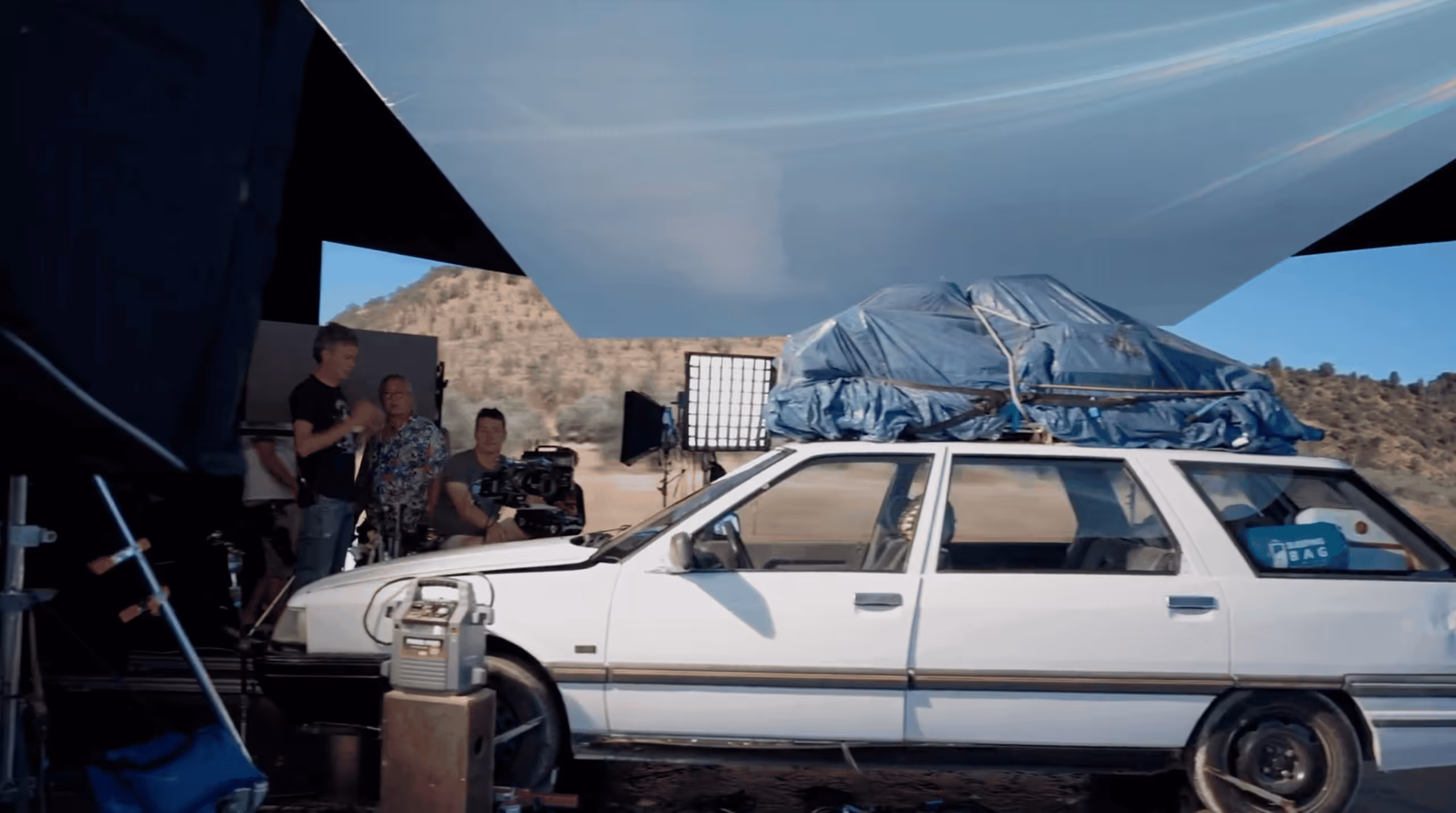
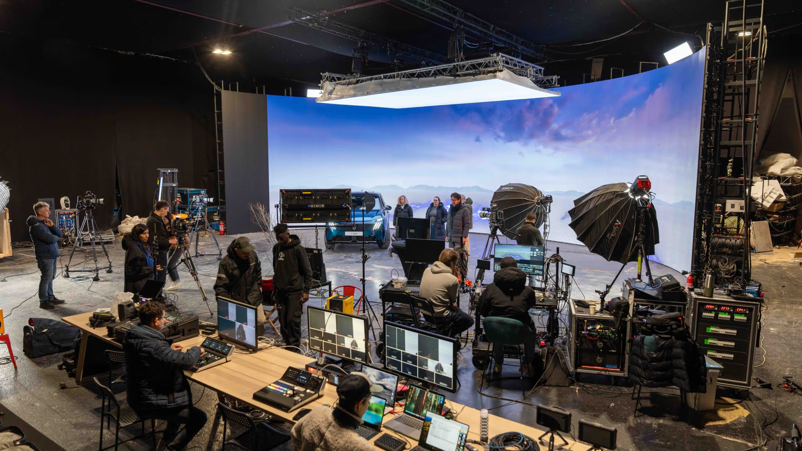
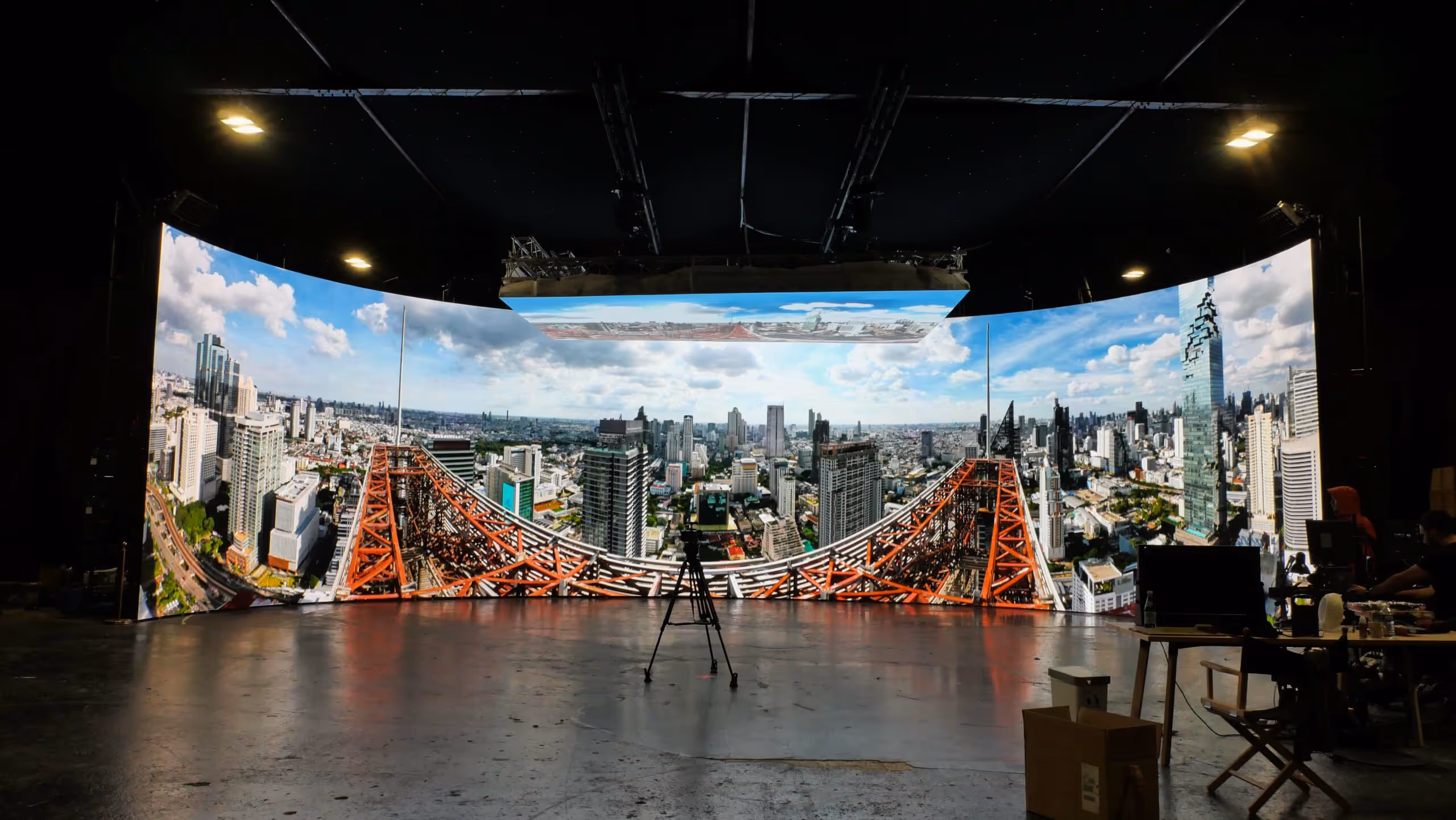
An XR LED Studio is a next-generation virtual production studio combining high-resolution LED walls, real-time 3D engines and camera tracking to create photorealistic immersive environments directly on set.
Street Co design and integrates custon XR LED studios for film, advertising, events and brand content.
And XR LED Studio transforms production workflows by offering real-time realism, creative flexibility and cost efficiency.
Key Benefits
Led walls display real-time 3D environments synchronized with the camera.
Virtual sets are generated in real time using engines such as Unreal Engine.
Camera movements are tracked precisely to adapt perspective and parallax.
LED screens naturally light the scene, reinforcing realism.

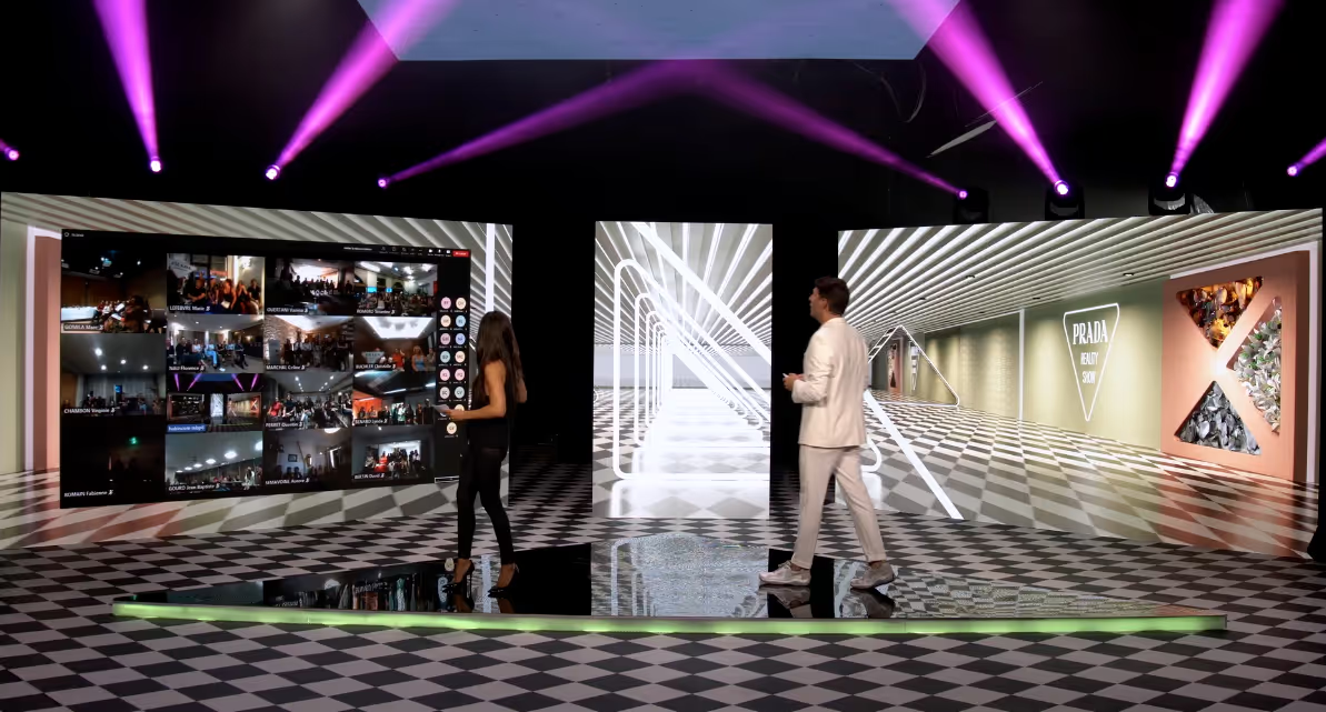
Indoor LED displays elevate spaces with seamless visuals, high brightness and sharp image quality. Perfect for retail, corporate and experiential environments, they bring dynamic content to life while integrating cleanly into modern interior design.
UPAD IV is Street Co’s professional media player designed to power LED installations with smooth playback, reliable performance and easy content control, ideal for retail, events and immersive digital experiences and XR Studios.
Virtual Production House is our XR virtual production studio based in Paris, built to deliver immersive, high-end content using real-time LED environments and a full production setup.
Street Co supports clients from concept to operation:
Each XR LED studio is designed to be reliable, scalable and production-ready.
Looking to design an XR LED Studio for your brand or clients?
Street CO helps create XR studios powered by LED technology.
How much does an XR LED studio cost?
The cost depends on LED volume size, pixel pitch, tracking technology and production requirements. Modular and compact solutions are available.
What is the difference between XRLED and green screen?
XR LED displays virtual envrionments in real time with natural lighting and reflections, significantly reducing post-production.
Is an XR LED studio suitable for small productions?
Yes, XR LED studios are perfectly suited for advertising, corporate and digital content.